Low-Damage Envelope Design
2021
An project Integrated with Architectural / Engineering / Practical Considerations.
A Research about Reducing Damage of Secondary Envelopes for Multi-Storey Timber Buildings during Earthquakes.
I am interested in building more sustainable and resilient societies.
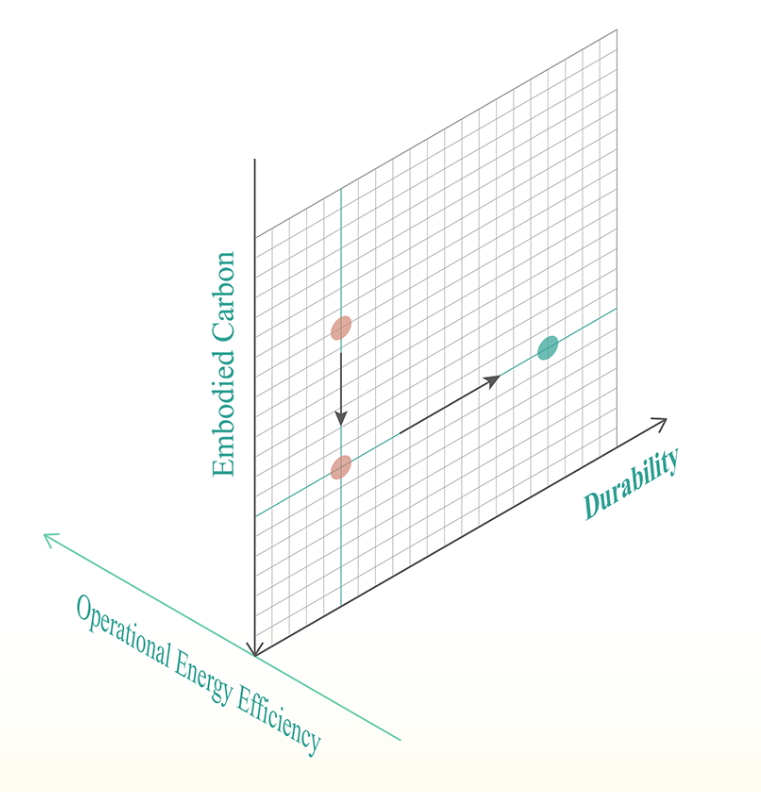
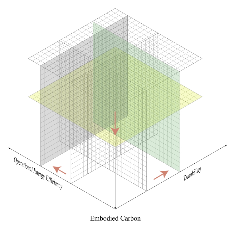
Due to climate change, active actions such as net zero emissions of all greenhouse gases by 2050 are being taken. What we can do is reducing Whole-of-Life Embodied Carbon, improving Transforming Operational Efficiency and enhancing Durability.
Urbanisation & Mass Timber Buildings
Due to urbanisation, an increasing population concentrates into urban areas, and multi-storey buildings play an indispensable role to mitigate the pressure. Unlike concrete and steel, timber has lower embodied carbon. Mass timber construction methods help to achieve multi-storey timber buildings.
Seismic Design & 2.5% Inter-Storey Drift
When facing earthquakes, building structures with all types of materials face the same issue of seismic movement. The buildings with ductile design can survive without collapsing. However, it causes deformation and damage. The primary deformation is inter-storey drift. In order to limit the damage, the standard allows an inter-storey drift of up to 2.5% of the floor height.
Low-Damage Design
In the Canterbury Earthquakes, more than half of multi-storey Reinforced Concrete (RC) buildings were demolished. Irrepairability or unusability were the common reasons for demolition. The society has more concerns about the buildings' post-earthquake condition. Low-damage design is one of the new ideas for seismic design that prevents elements from breaking or provides repairability and reusability, so they don't need to be demolished. Several low-damage timber structures have been proposed and used in New Zealand, such as limiting the drift by 1-1.5% or using proprietary products. The example here is the CoCA building in Wellington. It used post-tensioned timber, which allows the building to move more and dissipate the energy, but the envelope wasn't designed for moving. Therefore, the envelope might be damaged in earthquakes.
Environmental Cost after the Canterbury Earthquakes
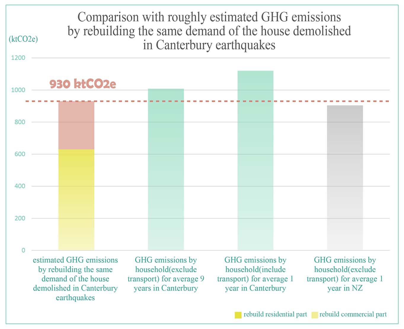
I was wondering what the carbon emissions were from the demolition, rebuilding and replacement after the earthquakes, but I found it hard to get the information of the environmental impact. Therefore, I made a rough and conservative estimation. If we rebuild the same amount of those demolished buildings, their total embodied carbon almost equals to 9 years of carbon emissions by households in Canterbury. This is significant.
Research Question:
How to reduce the damage of envelopes for timber buildings during earthquakes?
The challenge is : If the envelopes cannot accommodate movement such as drift, they break. The damage of the envelope causes several critical problems. For example, it is hard to take out the envelope if it has an installation sequence. The cost of repair is expensive and ignorance of it increases the risk of safety and deteriorates the building's performance.
Therefore, my thesis focused on low-damage envelope design which can accommodate a maximum of 2.5% drift without breaking.
Design Process
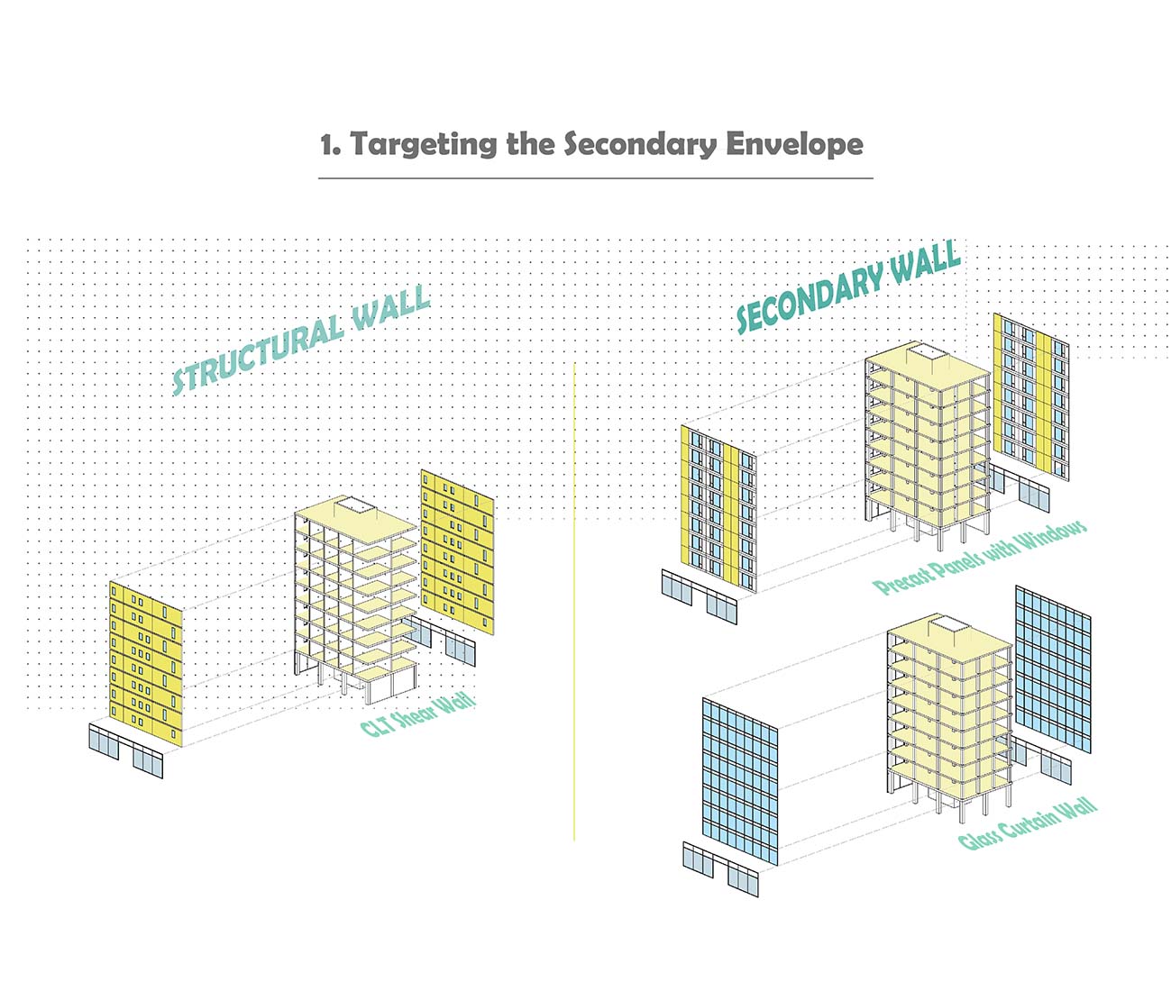
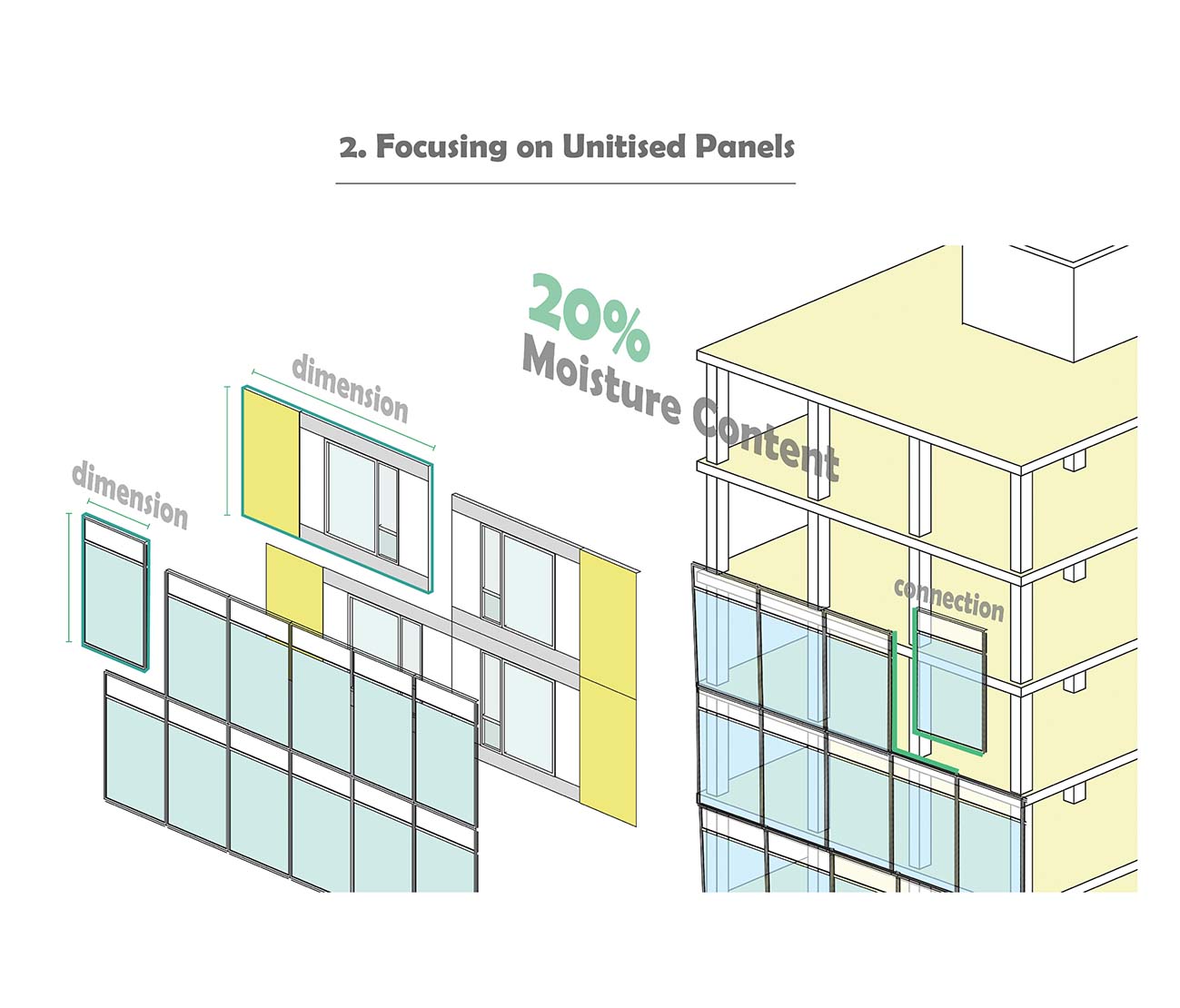
In terms of timber buildings, generally the moisture content of the timber should be kept under 20% for the entire service life to guarantee the durability. During construction time, the exposed timber needs to be protected from the weather as soon as possible. Using unitised panels can speed up the construction time and gives the timber more protection. The primary factors that influence the seismic and airtightness of unitised panels are the connections and dimensions.
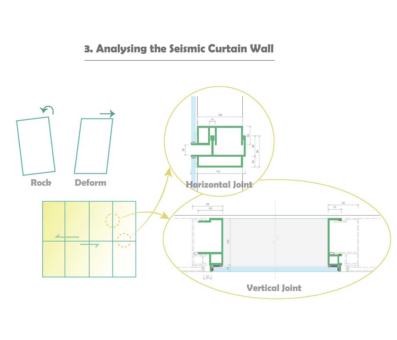
First, I analysed the existing seismic curtain wall. I talked to APL and Thermosash, which are the façade manufacturers. Glass curtain walls are usually designed in a smaller size due to the brittle property of glass. Because they are small and each panel are not fixed to each other, they are able to move or rock independently.
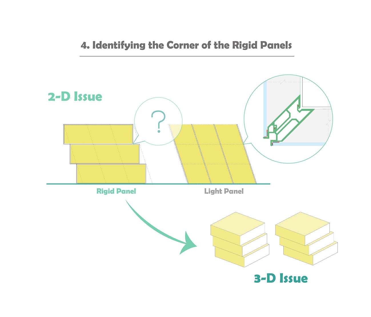
However, I was thinking, "How about a rigid panel, such as a bigger precast panel with windows?". I tried to make a rigid panel with slidable ability, but this panel is too rigid to rock or deform. I realised that there are some problems happening at the corner. So I went back to look at the corner of the seismic curtain wall, but it didn't look like it can solve this corner problem. I was also thinking that earthquake movements are three-dimensional issues, thus, I should also use three-dimensional methods to solve it rather than two-dimensional drawings.
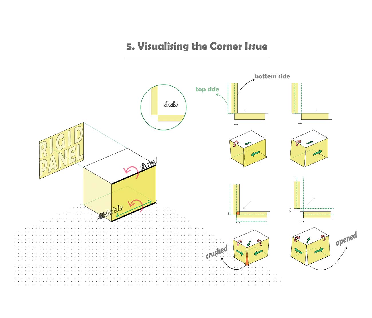
I built a dynamic 3D model with 2.5% drift to display the movement of slidable rigid panels. In the Grasshopper programme, the panel is set to be rigid and unable to deform. The top is fixed on the slab, which cannot move but can rotate. The bottom is not fixed, so it can slide in one direction and rotate.
If the panels collide with each others, they break. (This is not preferable.)
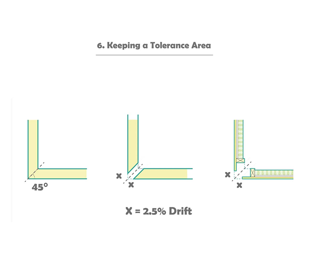
So the critical point is keeping a gap (x) to prevent them from colliding. "X" is set as 2.5% drift. If the floor height is 3 metres, x is 75 mm. When we consider the wall composition, the details of the corner is different.
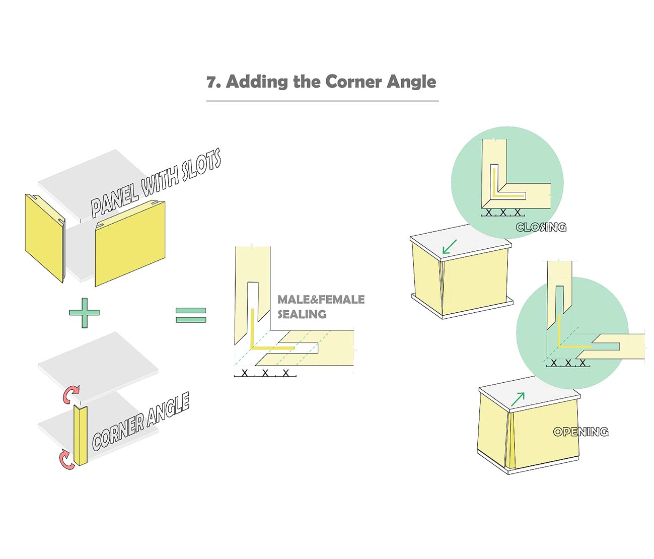
However, this makes the building have leakage. So I added a corner angel to seal the opening. The end of the panel needs to have a slot with 2 times (the length) of x and keep a x gap to the corner line. The length of each wing of the corner angel is 2 times of x. The corner angle is positioned on the top and bottom side, so it cannot move but only rotate.
The corner angle moves out or merges into the slots.
With this combination, the corner works for a slidable panel system.
Details
Modifying connections for unitised panels, especially at the corners, so the panels can slide in a controlled manner without breaking.
Initially, I developed three corner types for this system. The left one was the first corner that I designed. It is an aluminium corner, and it can work, but, its inter-storey joint has some problem of drainage. Water might go into the building. So I moved onto the two corners on the right. I finally settled down for the metal corner in the middle.
I wanted to keep it simple and I didn't remake a whole envelope system. The green parts are the existing seismic curtain wall panels and profiles. I used them directly and only modified a very small part of this system.
Demonstration Model
I applied these slidable panels to a timber-framed structure to explore how it works. This 4-storey timber-framed structure was designed and considered for a real commercial project in New Plymouth. The owner increased it to 7 storeys and it will be constructed in January 2022. This structure has 5 bays on each side, and it includes columns, beams and bracings. It has a constant height of 4 metres and 650.25 m² for each floor.
I assumed that the ground floor is for commercial use and the upper floors are for residential use, so that I could apply two types of panels. Small-sized glass curtain wall, and large-sized opaque panels. I also developed some potential details of different joints.
Environmental Benefit
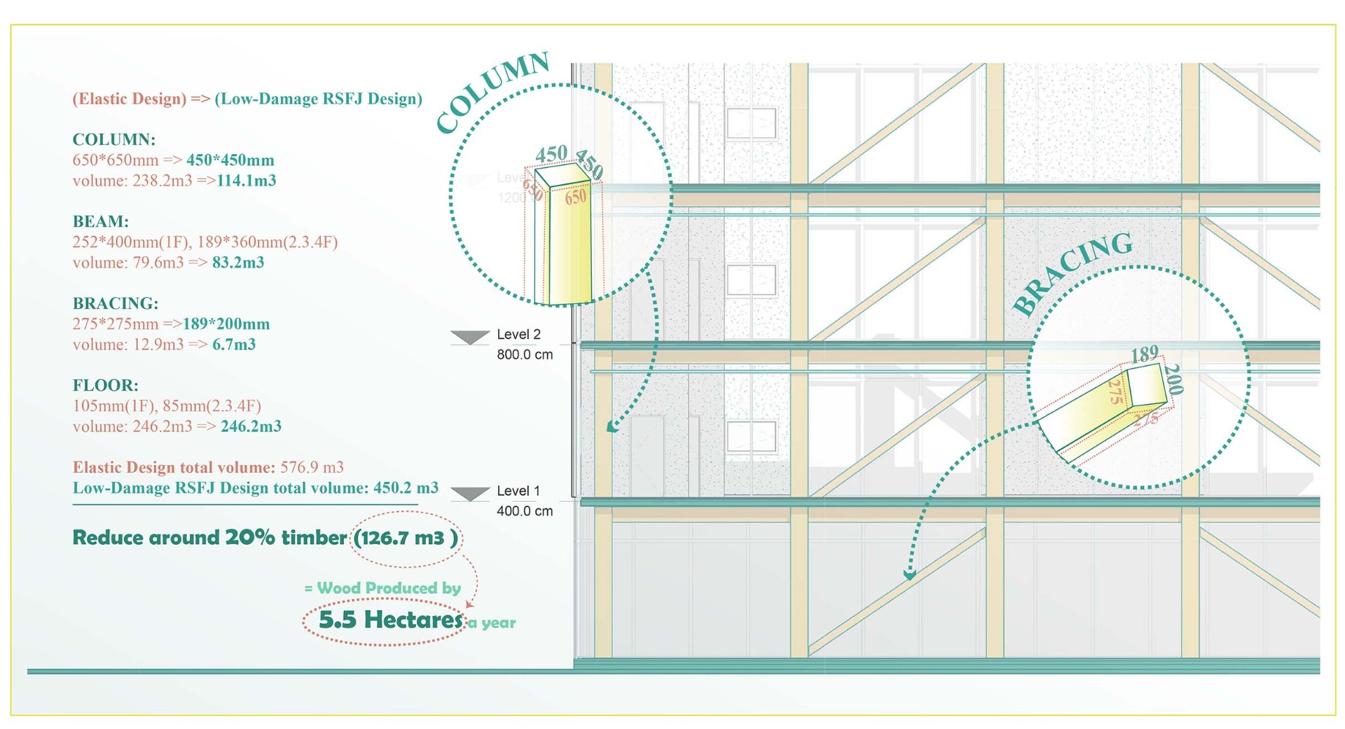
Currently, designers would restrict the drift by 1%. If we apply this low-damage envelope method, the drift can potentially move to 2.5%, by which, the structural timber can be more slender and can be cheaper. Therefore, more multi-storey timber buildings can be used in the market. In the published paper for this structure, it was designed for 1% drift. Two types of structural systems have been compared. The one with low-damage joint structure, shown in green, can save 126 m³ of timber. This equals to the wood produced by 5.5 hectares of pine forest a year.
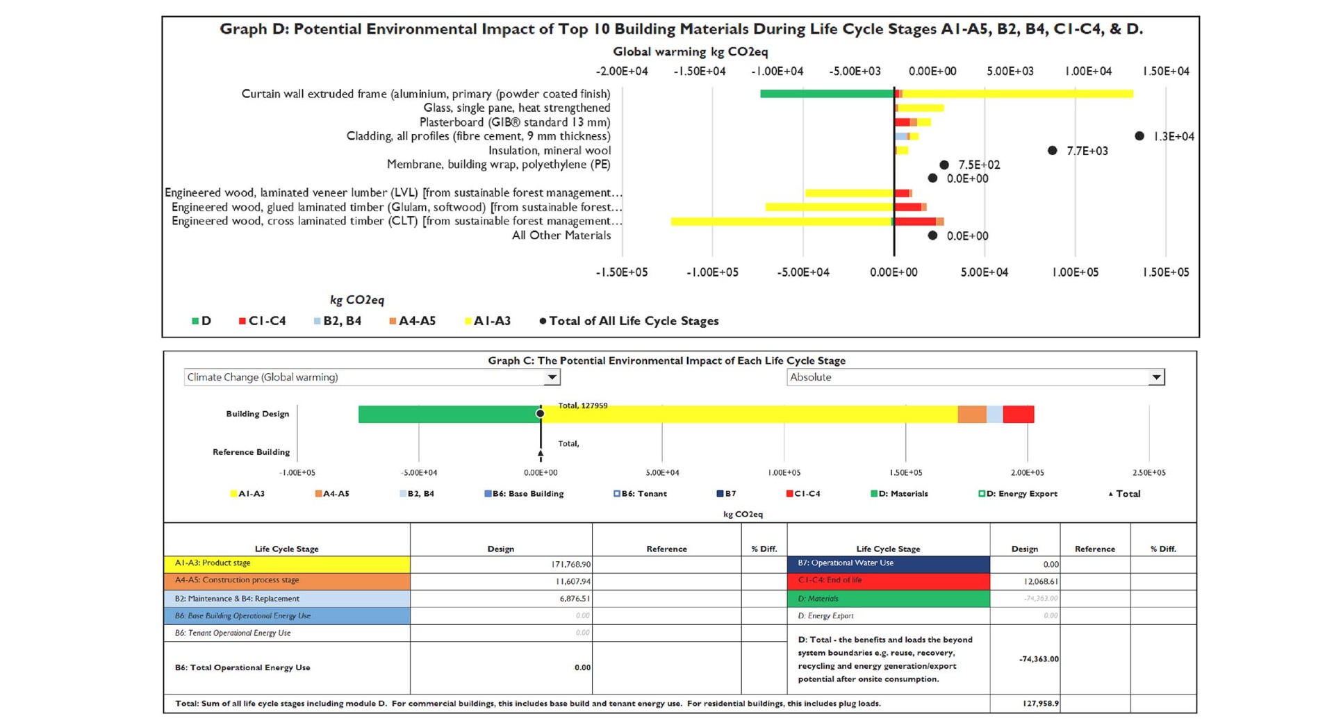
I also used LCAQuick to gain the result of global warming potential, which is the carbon footprint. LCA is Life Cycle Assessment. LCAQuick is an Excel-based free tool in New Zealand developed by BRANZ. It can evaluate the environmental impact and help designers make sustainable decisions.
I only used it for the envelope and structure. The picture on the top shows the carbon footprint by the different materials. The yellow bar represents A1-A3 production stage. If it goes to right, it emits carbon. If it goes to left, it offsets carbon. The top carbon contributor here is aluminium, but it has good durability. Therefore, it has an extra credit to offset the carbon, which is the green bar.
The bottom picture shows the carbon footprint of the envelope in this project. It is 128 tons CO²e in total.
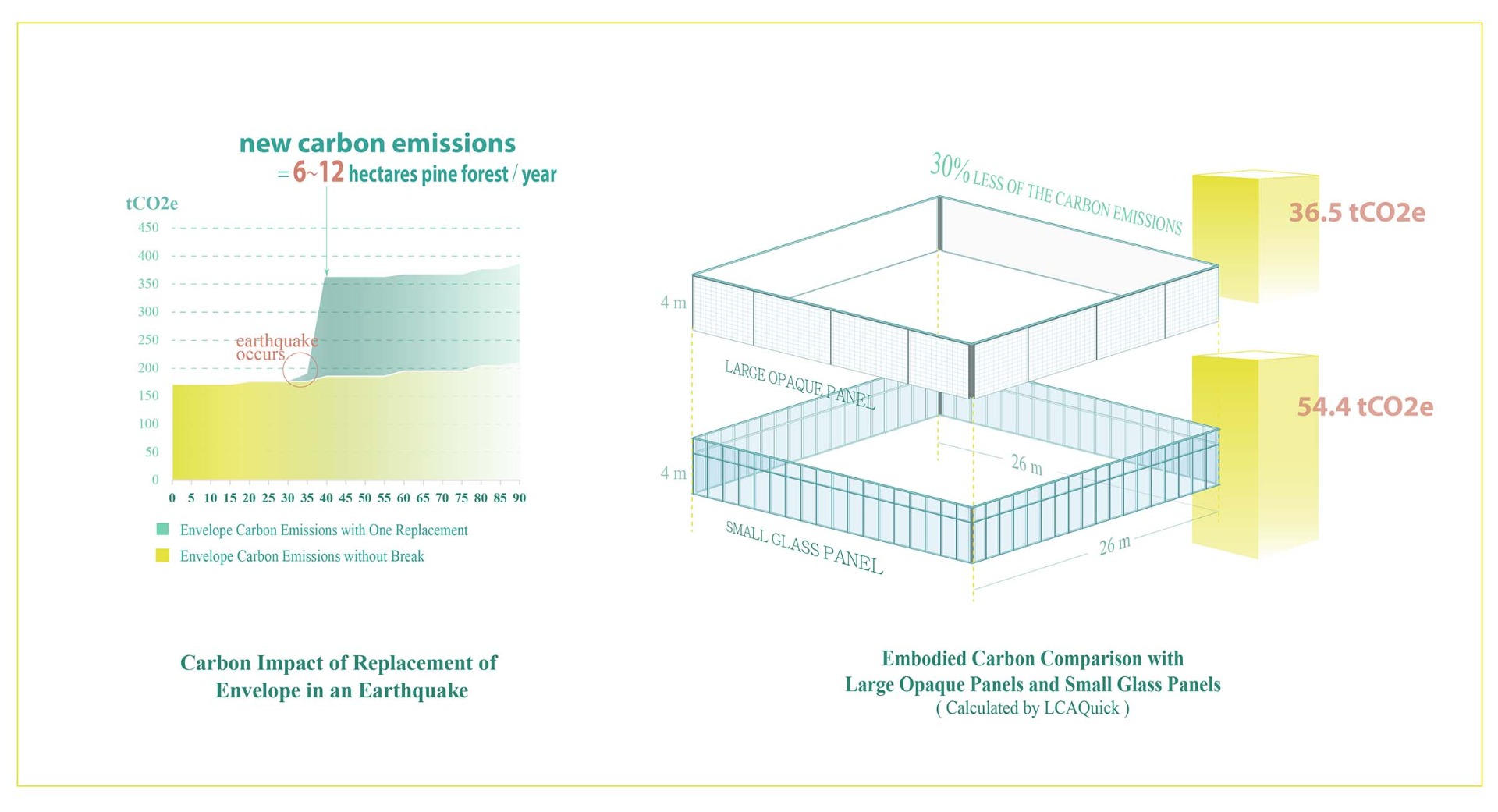
Let's look at the chart on the left. This low-damage envelope design doesn't aim to reduce its embodied carbon, but it can enhance the durability in earthquakes and potentially cut off the replacement. Like I calculated in the previous slide, the carbon emitted by this envelope requires 6-12 hectares of pine forest to absorb it for a year.
In the picture on the right, I compared the embodied carbon of the glass curtain walls and large opaque panels. The large opaque panels have less embodied carbon and also a better thermal resistance. However, most of the larger panels are more rigid and unable to accommodate the movement. Therefore, this slidable system provides the larger panels an opportunity to sustain in earthquakes.
(If the envelopes enhance their durability, they reduce the new carbon emissions from their replacement.) And if the panels remain in a good condition at their end-of-life, they can be directly used in other projects.
